
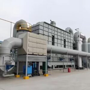
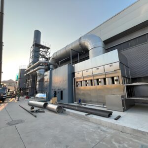
Catalytic Oxidizer (CO) | High-Efficiency VOC Abatement
Engineered for low-to-medium exhaust flows with superior energy recovery & catalyst technology.
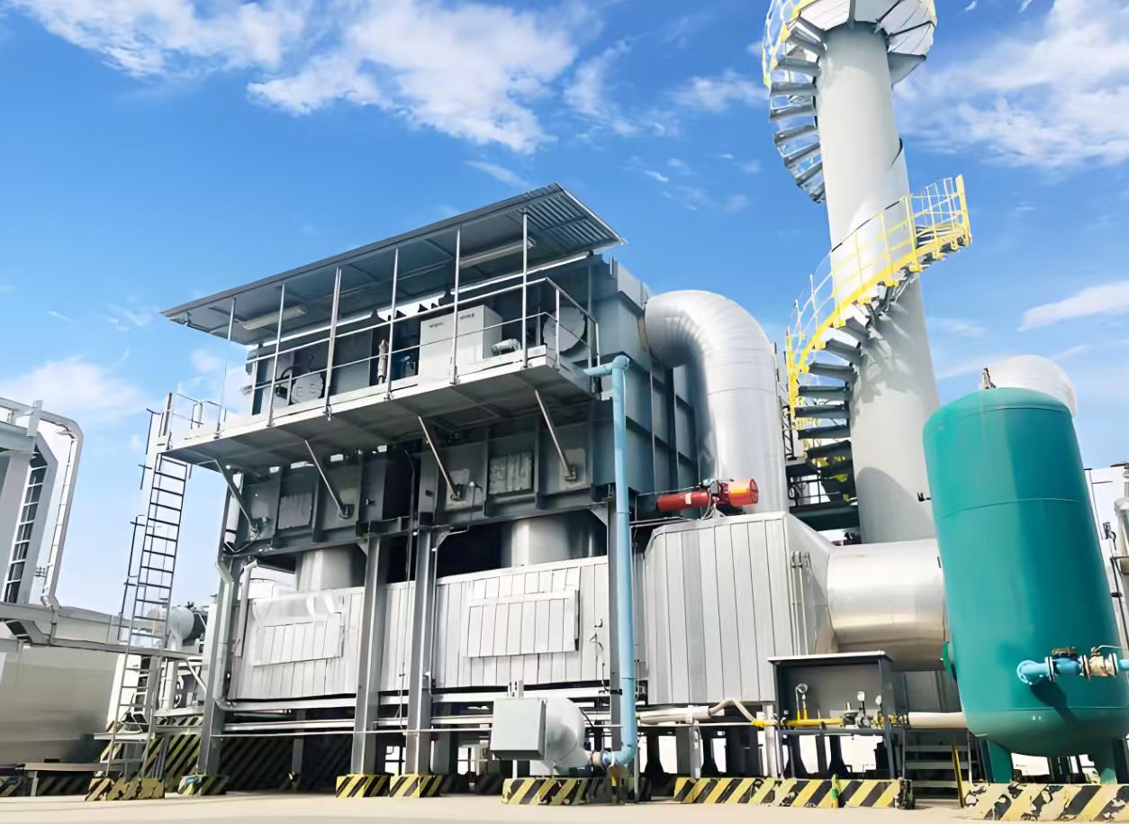
Unlike traditional RTOs with ceramic media, our CO unit does not incorporate a regenerator bed but instead integrates external or internal heat exchangers to preheat the incoming VOC-laden air. The hot side of the heat exchanger receives treated high-temperature flue gas, maximizing thermal recovery. Preheated process gas enters the catalytic combustion chamber where auxiliary energy (natural gas or electric heater) raises the temperature to catalyst light-off levels (250–350°C). VOCs are oxidized over the catalyst bed into CO₂ and H₂O, releasing heat. The purified hot flue gas then passes back through the heat exchanger(s) to preheat incoming air before being discharged to the stack — a truly energy-conscious design.
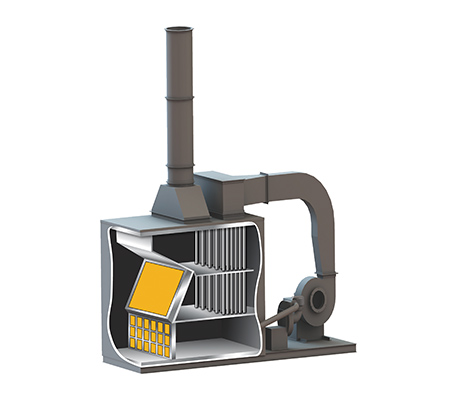
VOC Destruction Process & Heat Recovery
📌 VOCs Flow Path 1 – Rotor Concentration & Primary Heating
Driven by the desorption fan, low-concentration VOC gas from the cooling zone of the zeolite rotor enters the cold channel of the Stage 1 heat exchanger. The gas temperature rises from 60°C to 200°C after heat exchange, then flows back to the desorption sector of the rotor. The hot gas efficiently desorbs VOCs from the zeolite surface, creating a highly concentrated VOC stream (controlled below 10g/m³).
🔥 VOCs Flow Path 2 – Secondary Heating & Catalytic Oxidation
The high-concentration VOC gas (approx. 10g/m³) enters the Stage 2 heat exchanger cold channel, raising its temperature from 120°C to 300°C. It then flows into the catalytic combustion chamber. If the inlet temperature is below 300°C, the burner automatically ignites to ensure a range of 300–350°C before the catalyst bed. As VOCs oxidize over the catalyst (exothermic reaction), a temperature rise of ~250°C occurs (based on specific heat ~25°C per g/m³ VOC). Therefore, 300°C inlet gas reaches ~550°C after catalytic combustion. The purified hot air supplies heat to both Stage 1 & Stage 2 heat exchanger hot channels, then discharges via stack.
💨 Final energy recovery & reuse: After catalytic combustion, the clean high-temperature gas (≈550°C) sequentially releases its heat to the cold streams of both heat exchangers, maximizing thermal efficiency. Moreover, waste heat recovery design can be optionally integrated to supply hot water or space heating for manufacturing facilities — turning pollution control into a sustainable energy source.
✔️ Suitable Applications & Process Constraints
Ideal for
- Medium to high VOC concentration at relatively low to medium air flows
- Facilities with strict energy budget (gas/electricity saving priority)
- VOCs that are catalytically oxidizable (no catalyst poisons)
- Streams free of particulate & sticky substances that could foul catalyst surface
- Gases without dust-forming compounds after oxidation (prevents catalyst deactivation)
Industries & Compounds
Primary sectors: Paint & coatings, spray booths, printing, packaging, adhesives, chemical processing.
Typical VOCs handled: Ethyl acetate, propyl acetate, ethanol, aromatic hydrocarbons, ketones, and other oxidizable organics.
Printing
Coating lines
Lamination
📊 Technical Specifications
🎛️ Customization & Diverse Options
🔥 Heating Method
Choose between fuel-fired burner (natural gas / LPG) or electric heating elements based on site utility availability and carbon reduction goals.
🧪 Catalyst Types
Multiple options available: precious metal catalysts (Pt/Pd) for high activity, or non-precious metal catalysts (transition metal oxides) for cost-effective performance.
🌿 Post-treatment Integration
Easily couple with downstream systems: wet scrubber modules for acid gas removal, DeNOx unit (SCR/SNCR) for NOx control if required.
♨️ Heat Exchanger Variants
Based on thermal recovery needs, we offer shell & tube, plate-type, or customized primary/secondary heat exchangers to maximize energy saving and meet specific ΔT requirements.
🔄 Detailed VOC Pathway & Temperature Control Logic
Inside the catalytic combustion chamber, a temperature sensor verifies the VOC gas temperature after the secondary heat exchanger. If the gas is below 300°C (setpoint), the burner automatically ignites to provide supplementary heating, ensuring stable catalytic activity across a range of 300°C–350°C. After passing through the catalyst bed, flameless oxidation occurs, raising the gas temperature by as much as 250°C (for 10g/m³ VOCs). The resulting clean exhaust is first directed to the hot side of the Stage 2 heat exchanger, then to Stage 1, releasing thermal energy to preheat incoming VOCs. Ultimately the purified air is discharged to the stack, meeting stringent environmental standards.
⚡ Why Choose Our Catalytic Oxidizer?
💰 Lower Energy Demand
Low operating temperature (250–350°C) significantly cuts fuel/electricity consumption compared to thermal oxidizers (760°C+).
📦 Compact Design
No massive ceramic beds required; footprint efficient with integrated heat exchanger configurations.
📈 Flexible Configurations
Support for zeolite rotor pre-concentration, multi-stage heat recovery, and future expansion of post-treatment.
⚠️ Important Preconditions for Optimal Performance
- The waste gas stream must be free of catalyst poisons (e.g., heavy metals, halogens, phosphorus, silicon compounds).
- Particulate matter, tars, or sticky aerosols should be removed upstream to prevent catalyst fouling.
- Compounds that generate solid dust upon oxidation (e.g., certain siloxanes) must be pre-treated.
- For chlorinated VOCs, optional post-scrubber recommended to handle acid gas byproducts.
Note: Our engineering team provides comprehensive feasibility analysis — catalyst life, poisoning risks, and heat recovery potential — for every specific application.
Reviews
There are no reviews yet.