
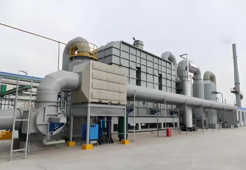
Regenerative Catalytic Oxidizer (RCO)
Advanced VOC abatement combining RTO energy recovery efficiency with low-temperature catalytic oxidation.
The Regenerative Catalytic Oxidizer (RCO) utilizes a catalyst to decompose VOCs into CO₂ and H₂O while recovering the heat released during oxidation through high-efficiency ceramic heat recovery beds. Key components include directional valves, regenerator beds (ceramic media), catalyst bed, and a supplemental heater. RCO is an innovative catalytic technology that merges the exceptional energy recovery of RTO with the low-temperature operation benefit of catalytic processes. Compared to conventional RTO, RCO offers lower self-sustaining concentration thresholds, reduced energy consumption, and lower furnace temperatures — leading to significantly lower operating costs.
Working Principle & Thermal Recovery Cycle
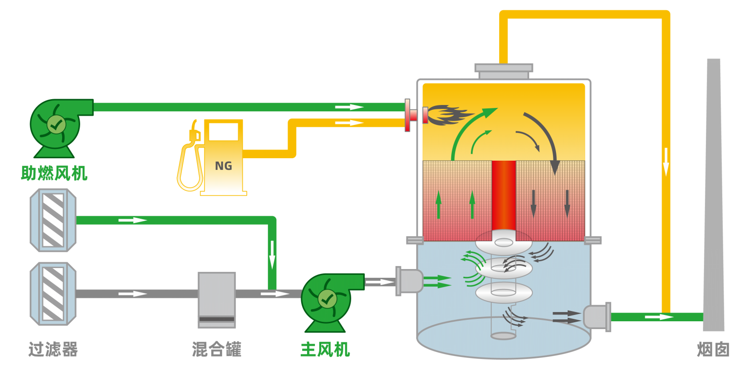
The heat recovery principle and switching sequence of RCO are largely identical to those of an RTO. VOC-laden exhaust gases from production processes pass through a ceramic heat recovery bed and are rapidly preheated. After entering the combustion chamber, an auxiliary burner (gas or electric) raises the temperature to the catalyst light-off range (250–300°C). The VOCs are then oxidized over the catalyst bed, breaking down into CO₂ and H₂O while releasing heat. The resulting high-temperature clean gas then flows through a second ceramic heat recovery bed (cold bed), transferring the stored thermal energy to the ceramic media. This preheats the next incoming batch of VOCs, drastically reducing auxiliary fuel demand. After passing the heat recovery beds, the flue gas may go through additional heat exchange systems before being discharged to the atmosphere.
📋 RCO Process Flow
VOC-laden exhaust is first introduced into the RCO system, passing through a pre-treatment unit to remove particulates, dust, and sticky aerosols that could foul the catalyst or ceramic media.
The pre-treated gas enters the ceramic heat recovery bed (Regenerator A) where it absorbs stored heat from the previous cycle, raising its temperature significantly before entering the combustion chamber.
The preheated gas (now near catalyst light-off temperature) flows into the catalytic reaction chamber. In the presence of the catalyst, VOCs react with oxygen and are converted into harmless CO₂ and water vapor, releasing exothermic heat.
The high-temperature purified gas passes through the second ceramic bed (Regenerator B), transferring most of its thermal energy to the media. The cooled, clean gas then exits the system, typically via a stack or further heat recovery loop. Flow direction is periodically reversed to maximize thermal efficiency.
✨ Key Advantages of RCO vs. Conventional RTO
1 Lower Auto-thermal Concentration
RCO can sustain self-sustaining operation at much lower VOC inlet concentrations due to catalytic reaction at 250–350°C, reducing auxiliary fuel consumption.
2 Reduced Operating Energy
Low furnace temperature (300°C typical) vs. 800°C+ for RTO means dramatically less fuel or electricity needed, lowering carbon footprint.
3 Mild Chamber Temperature
Lower thermal stress on components, longer equipment life, and safer operation with minimized NOx formation.
4 High Thermal Recovery
Ceramic regenerators achieve >95% heat recovery, identical to RTO, but with lower peak temperatures.
🔧 Main RCO Components
🏭 Applicable Industries & Ideal Applications
RCO excels in high air volume, low-to-medium VOC concentration scenarios. Typical industries include:
Shipbuilding
Motorcycle manufacturing
Bicycle coating
Home appliances
Container production lines
Petrochemicals
Rubber processing
Paint & coatings
Shoe adhesives & compounding
Plastic & rubber products
Printing ink
Cable & enameled wire
Metal decorating (can coating)
📐 Typical RCO Operating Parameters
🌿 Environmental & Economic Benefits
Because RCO operates at significantly lower temperatures than thermal oxidizers, it reduces fuel consumption by up to 60-80% compared to direct-fired thermal oxidizers and up to 30-40% compared to standard RTO for certain low-concentration streams. Additionally, lower combustion temperatures suppress thermal NOx formation, making RCO an ideal solution for regions with strict NOx emission limits. The catalyst enables flameless oxidation, enhancing safety and reducing maintenance costs.
🧪 Catalyst Options & Durability
- Precious metal catalysts (Pt/Pd): Highest activity, excellent for mixed solvent streams, typical lifespan 3–5 years with proper pre-filtration.
- Base metal oxide catalysts: Cost-effective for stable, sulfur-free applications; durable and resistant to thermal aging.
- Proper pre-treatment (particulate removal, poison guard bed) can significantly extend catalyst life and maintain efficiency.
- Optional on-stream cleaning or off-line regeneration available for specific applications.
🔧 Custom Engineering & Supplementary Modules
Pre-concentration Rotor
Zeolite rotor integration for ultra-dilute exhaust streams to boost VOC loading before RCO inlet.
Post-treatment Scrubbing
Wet or dry scrubber for acid gas removal (when treating chlorinated VOCs) and particulate polishing.
Waste Heat Boiler
Additional heat recovery for steam/hot water generation using the final cleaned gas stream.
Reviews
There are no reviews yet.